 |
|
|||
 |
opens in a new window |
|
• The EFR product line is a wide range of all-new performance turbochargers from BorgWarner. They contain the highest level of technology currently available to aftermarket customers.
|
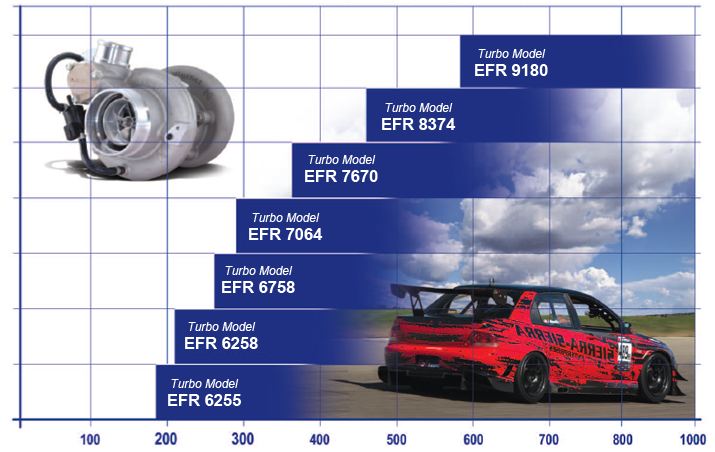
EFR Series Turbocharger Application Range |
||||
 |
||||
Engine Peak Horsepower |
EFR TURBOCHARGERS FOR UNIVERSAL FITMENT
VEHICLE SPECIFIC
EFR TURBO "COMPRESSOR COVER FEATURES"
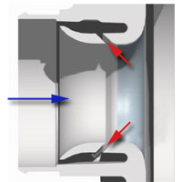 |
Anti-Surge Compressor Cover Inlet | |||
|
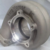
This casting is used with the 70mm and 76mm compressor wheels and features a recirculation groove. This groove surrounds the leading edge of the compressor wheel and provides an escape path for air on the tip of the wheel. In the process, the surge margin is extended when operating on the left side of the compressor map. On the right side of the map the operating range is also extended. In this zone, air is admitted through the port and into the wheel. The function of the recirculation groove is very different than that of the CRV (below). The recirculation groove is in operation all the time. The CRV operates only during a throttle-closing event and helps prevent compressor backflow and related compressor surging. The inlet connection on this cover is sized for a 3.5” hose and the outlet is for 2” hose. Otherwise, it’s very similar in size and shape to the small cover. |
| Compressor Cover Outlet Connections |  |
|||
|
There are three compressor cover types: The “small, A” cover is used with the 62mm and 67mm wheels and has a 2.5” inlet hose connection and a 2” outlet hose connection. The “medium, B” cover is used with the 70mm and 76mm wheels and has a 3.5” inlet hose connection and a 2” outlet hose. The “large, C” cover is used with the 83mm and 91mm wheels and has a 4” inlet hose connection and a 2.5” outlet hose. The “large” cover has a dual-machined outlet, both for a hose connection and a v-band connection. If the v-band feature is needed, the hose connection portion can be cut off and discarded. |
|
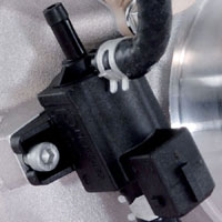 |
Integrated Boost Control Solenoid Valve (BCSV) | |||
|
Integrating the boost control solenoid valve (BCSV) onto the compressor cover is another feature that has been widely used for a few years on OE applications. Any user of electronic boost control will need a solenoid valve. We use the highest quality part with OE-level robustness for this application. It is a value to the customer to buy it as part of the assembly so that they save money overall as well as have a tidy mounting solution. Loose BCSV’s will also be sold as a service item in case the original one is damaged. The solenoid valve uses an “injector type” connector, and the BSCV connector itself is marked with a polarity symbol. There are two connections, +12V and ground. The valve is pulsewidth controlled and the wave frequency should be less than or |
| Integrated Compressor Recirculation Valve (CRV) | 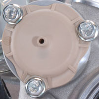 |
|||
|
BWTS has had great success with integrating the compressor recirculation valve (CRV) into the compressor cover for quite a few years on OE petrol engine applications. The major benefits are of course the underhood packaging space that is freed up by not having an external device and the cost savings from integrating it into the turbo assembly. Recirculating the flow back into the compressor inlet helps keep MAF engine management systems “happy” and also helps keep turbo speeds high during the shift. The only downside of this feature is the fact that it makes the compressor housing about 1” longer in axial length. For the users that opt not to use the internal valve, we offer a disabling cover plate. This cover plate installs in place of the plastic cover and |
 |
Integrated Speed Sensor Mount | |||
|
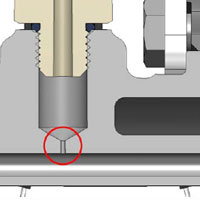
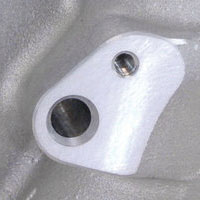
Turbo speed sensors are of course not new technology, but the installation procedure has often (or perhaps always) been difficult for the end user. Competing products require the customer to remove their compressor cover and take it to a machinist. This machinist then has to set up the cover at a compound angle to precisely drill the speed sensor bore while carefully hitting the contour area of the wheel bore and at the right angle. |
EFR TURBO "COMPRESSOR WHEEL FEATURES"
| Forged Milled Compressor Wheels | 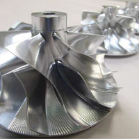 |
|||
|
The series of compressors is from 62mm to 91mm OD satisfies a wide range of applications. The compressor wheels are all FMW (forged milled wheels). BWTS selected forged milled wheels not because they are pretty (even though they are) but because they do offer a strength improvement over cast wheels and because it provides speed and flexibility to the design process by not having to make casting tooling. Most high performance users won’t benefit from the strength improvement because these applications are generally low turbo rotational speed and of relatively short mileage lifetime as compared to a commercial application. But, for the endurance racer or the uber-boost drag racer, the material might save your day. The compressor covers have been given BWTS's latest flow-range enhancement tricks such as treatment to the recirculation slot and optimization of the diffuser pinch and width. |
 |
Extended Tip Technology | |||
|
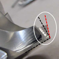
Through a high backsweep angle on the blade outlet and the BWTS Extended Tip Technology on the exducer tip, these wheels offer excellent range (flow capacity) while still being capable of high boost at reliable turbo speeds. These Extended Tip Technology wheels are very unique in that they are BWTS's highest-boost capable wheels but still give outstanding map width and flow capacity. |
EFR TURBO "ACTUATOR FEATURES"
| Mounting Options | 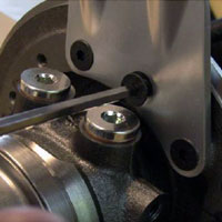 |
|||
|
The canister bracket connects to the front face of the bearing housing, on the compressor end. This is a relatively cool location and keeps heat conduction (to the actuator) to a minimum. Furthermore, both the bracket and the output rod are stainless steel which further reduces the conducted heat. The bolt pattern on the bearing housing face is drilled in 15° increments which maximize the canister mounting options. Since the actuator mounts to the bearing housing, the bracket location will have to be adjusted simultaneously when the turbine housing to bearing housing orientation is adjusted. |
 |
||||
|
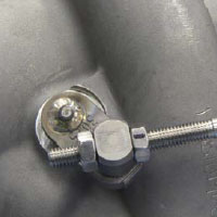
Avoid twisting the rod while tightening the adjustment nuts. Hold the rod steady while turning the nuts. The rod threads are 1mm pitch, so each turn of the nut equals a 1mm change in preload. We recommend at least 2mm of preload applied to the rod. This applies force to keep the wastegate valve held closed, and also prevents premature vibration wear of the canister internals. |
|
